
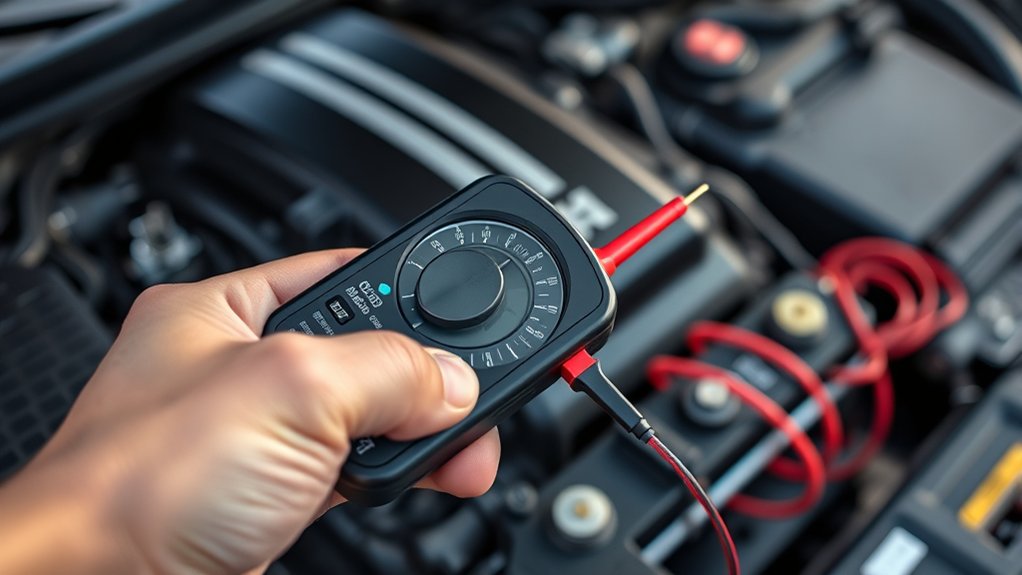
How Does an Automotive Multimeter Work Step by Step
Diagnosing car electrical problems can feel frustrating, especially when you’re unsure which reading to trust. You’re not alone—many people struggle to use an automotive multimeter confidently. The right meter can make testing faster, safer, and much easier.
To use an automotive multimeter, turn it on and select the required function: DC voltage, resistance, continuity, or current. Plug the black lead into COM and the red lead into the correct jack. Touch the probes to the test points, then check the displayed value, units, polarity, and range.
Test voltage on powered circuits, but measure resistance or continuity only with power disconnected. Compare results with vehicle specifications to identify faults. The steps below explain each test safely.
Key Takeaways
- Turn on the multimeter, select the required function, and choose AC voltage, DC voltage, resistance, continuity, or current.
- Insert the black probe into COM and the red probe into the appropriate voltage, resistance, or fused current jack.
- Connect probes correctly, keeping black negative and red positive for voltage measurements while avoiding moving or hot engine parts.
- Measure battery or charging voltage in parallel, continuity or resistance only on unpowered circuits, and current in series.
- Read the displayed value, units, polarity, and warning symbols, then compare results with vehicle specifications to identify faults.
Learn the Automotive Multimeter’s Main Controls

Before you begin testing, learn what each control does. Start with the power button, then identify the rotary dial and its symbols. The dial selects the instrument’s general function, while separate buttons may adjust range, hold a reading, or activate backlighting.
Learn each control before testing: power on, set the rotary function, and understand range, hold, and backlight buttons.
Find the common jack and the dedicated jacks for voltage, resistance, and current leads. Check the probe markings and match each lead to the correct jack before connecting anything.
Inspect the display for units, polarity, low-battery alerts, and warning icons. Learn how the fuse indicator and overload message appear, so you’ll recognize unsafe conditions quickly.
Read the manual to confirm input limits and lead ratings. Automotive safety depends on preventing accidental shorts and excessive current. Keep the meter clean, dry, and free from damaged insulation.
Finally, verify Multimeter calibration according to the manufacturer’s schedule. Accurate calibration supports reliable troubleshooting, while disciplined control checks help you work confidently before connecting the meter to a vehicle.
Understand Automotive Multimeter Measurement Modes
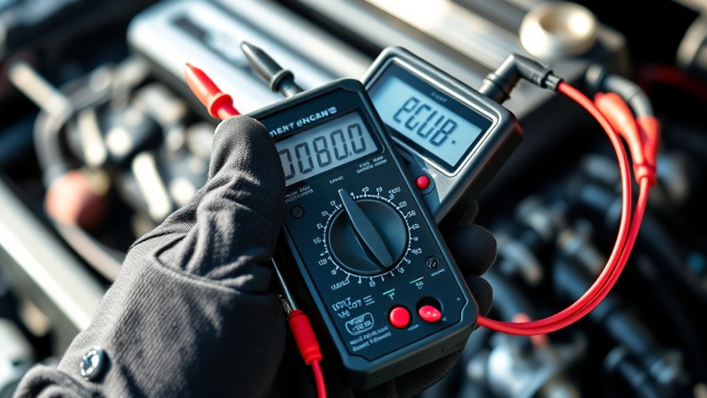
Use voltage mode to check electrical potential in your vehicle’s circuits. Switch to resistance mode when you need to test component values, and use continuity mode to confirm that a connection is unbroken. Next, you’ll learn when and how to use each setting safely.
Voltage Measurement Mode
In voltage measurement mode, an automotive multimeter measures the electrical potential difference between two points in a vehicle circuit. You select AC or DC voltage, then choose a range that exceeds the expected reading.
Connect the black probe to a suitable ground and touch the red probe to the test point. Your meter displays voltage, helping you evaluate battery condition, charging output, reference signals, and voltage drops across powered components.
Always connect probes in parallel, keep leads clear of moving parts, and avoid exceeding the meter’s rated input. You can use min/max functions to capture changing signals during cranking or operation.
During sensor calibration, compare measured voltage with the manufacturer’s specifications. Data logging lets you record readings over time, revealing intermittent faults that a single observation might miss.
Resistance And Continuity Modes
Resistance and continuity modes let you check whether a circuit or component offers the expected electrical path. Set your multimeter to ohms (Ω) for resistance, then touch the probes across the isolated component. The display shows resistance in ohms; a high or infinite reading indicates an open circuit, while a low reading may indicate a short.
For continuity, select the sound-wave symbol and probe both sides of a wire, fuse, switch, or connector. A beep confirms a low-resistance path, but silence suggests a break.
Always switch off ignition power and disconnect the battery when appropriate for automotive safety. Never measure resistance on a live circuit.
Before testing, inspect leads and consider multimeter calibration, especially when precise resistance values matter. Compare readings with the vehicle’s service specifications.
Choose the Right Automotive Multimeter Setting

Choose the setting that matches the electrical value you need to measure: voltage (V), current (A), or resistance (Ω). Select DC voltage for most battery, alternator, and vehicle circuit checks. Use AC voltage only when the system produces alternating current, such as certain sensors or charging components.
Choose the current setting when you need to measure amperage, and verify the meter’s maximum rating first. High-current measurements require the correct input and fuse, so automotive safety depends on selecting both the proper mode and range.
Never use the current mode casually, because an incorrect application can damage the meter or vehicle circuit.
Select resistance or continuity for unpowered components and wiring. Resistance mode helps you compare component values, while continuity mode confirms a low-resistance path with an audible tone.
Check Multimeter calibration when readings seem inconsistent, and replace weak batteries before testing. If your meter offers automatic ranging, use it for convenience. Manual ranging can provide faster, more precise readings.
Connect the Automotive Multimeter Leads Safely
Before testing, plug the black lead into the COM jack and the red lead into the terminal that matches your selected measurement. Push each connector firmly into place, and inspect the probe insulation for cracks, exposed wire, or loose tips. Replace damaged leads before continuing.
For Automotive safety, keep your fingers behind the probe guards and hold only insulated portions. Don’t let the metal tips touch each other while they’re connected to a powered circuit.
Check the meter’s ratings, fuse condition, and lead category rating to ensure they match the vehicle system and test type. Keep leads away from belts, fans, hot exhaust parts, and sharp edges.
Confirm Multimeter calibration and select the correct function before touching any test point. If you’re measuring current, use the dedicated current jack and begin with the highest range.
Return the red lead to the voltage jack immediately afterward. Disconnect power before changing connections or moving leads between terminals. Store the probes neatly to prevent future damage.
Measure Your Car Battery Voltage
To measure your car battery’s voltage, set your multimeter to DC voltage. Then, connect the red test lead to the positive battery terminal and the black lead to the negative terminal. Finally, read the voltage shown on the display.
Set Up the Multimeter
Start by setting your multimeter to DC voltage, typically marked “V⎓” or “DCV,” and select a range above 12 volts if the meter isn’t autoranging. This setting prepares you to check your car battery safely and accurately.
If your meter offers separate ranges, choose 20 volts DC, which comfortably covers a healthy 12-volt battery and possible charging voltage.
Before measuring, inspect the display, selector dial, and input markings for damage or confusion. Automotive diagnostics depend on choosing the correct function, since resistance or current settings can produce misleading readings or damage the meter.
Check your user manual if symbols differ between models. For dependable results, verify Multimeter calibration according to the manufacturer’s instructions.
Let the meter’s display stabilize, and ensure its batteries have sufficient charge before beginning the test.
Connect the Test Leads
With the meter set to DC voltage, plug the black lead into the COM port and the red lead into the V or VΩ port. For safe Automotive diagnostics, switch off the ignition and keep metal probes from touching each other.
Check your Multimeter calibration first, then locate the battery’s positive (+) and negative (–) posts. Hold the insulated probe handles, not the metal tips, and prepare to make firm contact.
| Lead | Connection | Purpose |
|---|---|---|
| Black | Negative (–) post | Completes the circuit |
| Red | Positive (+) post | Measures battery potential |
Touch the black probe to the negative post and the red probe to the positive post. Keep both tips steady, and don’t force them against corroded terminals.
If your leads or ports look damaged, stop and replace them before continuing.
Read Battery Voltage
Turn the ignition off and read the number on the display once the probes make firm contact. Place the red probe on the positive battery terminal and the black probe on the negative terminal.
Set your multimeter to DC voltage, usually marked V⎓, and select a range above 12 volts if it isn’t automatic. A healthy, fully charged battery should show about 12.6 volts with the engine off.
Readings near 12.2 volts indicate partial discharge, while anything below 12 volts suggests a weak or drained battery. Don’t start the engine during this test, because charging voltage will produce a different result.
Check your owner’s manual for specifications, and consider Battery calibration if readings seem inconsistent. After testing, disconnect the probes safely and follow proper multimeter storage instructions to protect the tool.
Test Alternator Charging Voltage
To test alternator charging voltage, set your multimeter to DC volts. Connect the red probe to the battery’s positive terminal and the black probe to the negative terminal, then check the reading with the engine off and running.
First, note the engine-off voltage, which should typically measure about 12.4 to 12.7 volts in a charged battery.
Start the engine and let it idle without accessories. The reading should usually rise to approximately 13.8 to 14.7 volts, showing that the alternator supplies charge.
Turn on the headlights, blower, and rear defroster, then watch for a stable reading. A substantial drop may indicate a weak alternator, slipping belt, poor connection, or charging-system fault.
Don’t rev the engine excessively. Follow your vehicle’s specifications for exact limits.
This test supports battery maintenance and provides useful engine diagnostics. Record your results and compare them with the manufacturer’s recommended range before replacing any component.
Disconnect the probes carefully after shutting the engine off.
Check Continuity and Resistance in Circuits
Set your automotive multimeter to continuity mode, then touch one probe to each end of the circuit. If the meter beeps, the circuit usually has a complete path. If there’s no sound, the circuit may be open or broken.
To measure resistance, switch the multimeter to ohms and compare the reading with the vehicle manufacturer’s specifications.
Test Circuit Continuity
When you need to verify an unbroken electrical path, set your automotive multimeter to continuity mode and touch one probe to each end of the circuit or component. A beep or near-zero reading indicates that current can travel between the points.
Before testing, switch off the vehicle, remove the key, and disconnect power to protect yourself and the meter. Automotive safety comes first, so never use continuity mode on an energized circuit.
Confirm proper multimeter calibration and inspect the leads for damage. Use the test to locate breaks, loose connections, blown wires, or faulty switches.
Check each section systematically, then compare results with the wiring diagram.
- No beep usually signals an open path.
- An intermittent tone may reveal a loose connection.
- Restore power only after testing ends.
Measure Resistance Levels
Set your automotive multimeter to the resistance (Ω) range, then place the probes across the de-energized circuit or component. Don’t measure resistance on a live circuit; you could damage the meter or vehicle electronics.
Touch each probe firmly to the terminals, then compare the reading with the service specification.
| Reading | Meaning | Action |
|---|---|---|
| 0–1 Ω | Good continuity | Proceed |
| OL | Open circuit | Inspect wiring |
| High Ω | Excess resistance | Check connections |
| Specified Ω | Normal component | Reinstall |
For accurate results, disconnect one component lead so parallel paths don’t affect the measurement. Test wiring section by section, and gently flex harnesses to reveal intermittent faults.
Record values during sensor calibration and use Data logging to track changes over time. Always return the meter to voltage mode before reconnecting power.
Measure Current Without Blowing a Fuse
Measure current safely by plugging the red lead into the correct amperage jack, selecting the highest current range, and placing the meter in series with the circuit. Turn off the vehicle before breaking the circuit, then connect the leads securely.
Always use the correct amperage jack, highest current range, and a series connection with the vehicle powered off.
Never place the meter across the battery or another power source while set to current; that creates a short and can blow the meter’s fuse.
For automotive safety, check the meter’s input rating and inspect its internal fuse before testing. Multimeter calibration also matters: use a recently verified meter so protection features and readings remain trustworthy.
- Start on the highest amperage setting, then step down only when necessary.
- Keep test time brief, especially on high-current circuits.
- Disconnect power before moving the red lead to a different jack.
After testing, switch the lead back to the voltage jack and select a safe default mode. This habit prevents accidental shorts during your next diagnostic task and protects both the meter and the vehicle wiring.
Interpret Voltage, Resistance, and Current Readings
Once you’ve finished measuring current and returned the lead to the voltage jack, read each result according to the function you selected. For voltage, check the unit, polarity, and decimal position. A steady positive value shows the measured potential difference; a negative value means your probes are reversed. Compare the reading with the vehicle’s service specifications and consider whether the circuit is loaded or at rest.
For resistance, make sure power is off before interpreting ohms. “OL” usually indicates an open circuit or a value beyond the meter’s range, while a near-zero reading indicates very little resistance. Keep in mind that connected components can affect the displayed value.
For current, note amperes or milliamperes and confirm that the selected range matches the input. Fluctuations may reflect changing electrical loads. Accurate Automotive diagnostics depend on sound Multimeter calibration, clean probe contact, correct range selection, and proper unit interpretation. Record readings with their conditions so you can compare them consistently.
Use Multimeter Results to Find Electrical Faults
Use the reading pattern to narrow the fault instead of judging one value in isolation. For automotive diagnostics, compare your multimeter results with the vehicle’s specifications and a known-good circuit.
A low voltage reading may indicate a weak battery, poor connection, blown fuse, or excessive resistance. Test each section from the power source toward the load, then repeat the measurement under operating conditions.
- No voltage: Check the fuse, switch, wiring, and ground path.
- Low voltage: Look for corrosion, loose terminals, damaged wires, or voltage drop.
- Normal voltage, no operation: Test the component’s resistance, ground, and control signal.
For electrical troubleshooting, switch the circuit off before measuring resistance or continuity. Don’t condemn a part until you’ve confirmed its power and ground.
Wiggle connectors while watching the display to reveal intermittent faults. Record every reading, including test conditions, so you can spot changes.
This step-by-step method helps you isolate the failure instead of replacing parts unnecessarily.
Frequently Asked Questions
How Often Should an Automotive Multimeter Be Calibrated?
You should calibrate your automotive multimeter at least once a year, or according to the manufacturer’s guidance. Increase calibration frequency to every six months if you use it professionally, expose it to harsh conditions, or rely on highly precise readings.
Include calibration in your regular multimeter maintenance routine, especially after drops, repairs, or noticeable measurement errors. Keep records of each service, and use a certified laboratory or qualified technician for dependable results.
Can an Automotive Multimeter Diagnose Electronic Control Module Communication Problems?
An automotive multimeter can help diagnose electronic control module communication problems, but it won’t read network messages like a scan tool. Think of it as a stethoscope for your vehicle’s wiring.
You can measure power, ground, resistance, and voltage changes on communication circuits, supporting ECU troubleshooting and circuit analysis. Check for opens, shorts, poor grounds, and abnormal bus voltage.
For codes, data frames, and network testing, you’ll still need a compatible scan tool or oscilloscope.
What Safety Gear Should You Wear When Using an Automotive Multimeter?
Wear Safety glasses to protect your eyes from sparks, battery acid, and flying debris. Use Protective gloves rated for automotive electrical work, especially when handling batteries, damaged wiring, or hot components.
Choose insulated, snug-fitting gloves that preserve your grip and won’t catch on moving parts. Wear closed-toe, nonconductive footwear, and avoid jewelry or loose clothing.
Before testing, make certain your gear stays dry and inspect it for damage.
How Do You Replace a Damaged Multimeter Probe or Test Lead?
Replace a damaged multimeter probe or test lead by first switching off the meter and disconnecting it from every circuit. Inspect the connector and meter rating, then choose a replacement with matching plugs, category rating, insulation, and test lead compatibility.
For probe replacement, unplug the old lead, insert the new one firmly, and check continuity before testing. Don’t use cracked insulation, exposed conductors, loose plugs, or makeshift repairs, especially around energized automotive systems.
Can Extreme Temperatures Affect Automotive Multimeter Accuracy?
Yes, extreme temperatures can affect your automotive multimeter’s accuracy. Heat may change internal resistance, while cold can slow displays, weaken batteries, and alter component behavior.
Check the manufacturer’s operating range before testing. Let the meter reach room temperature, keep it dry, and avoid leaving it inside a hot vehicle.
Temperature sensitivity varies by model, so increase calibration frequency if you regularly work in harsh conditions. Replace inaccurate instruments or have them professionally calibrated.
Conclusion
With an automotive multimeter, you can follow the electrical clues your vehicle leaves behind. You’ll select the right mode, connect the leads safely, and test voltage, resistance, continuity, or current.
Then, compare each reading with the manufacturer’s specifications. Like Sherlock Holmes following a trail, you’ll use those numbers to narrow down the fault instead of guessing.
Handle the meter carefully and verify your settings before testing. By learning how an automotive multimeter works step by step, you can turn confusing electrical problems into clear, manageable repairs.