

How Does a Circuit Tester Work Step by Step
When you’re troubleshooting wiring, a dead outlet, or an automotive electrical problem, choosing the right circuit tester can feel overwhelming. You’re not alone—many people struggle to know which tool is safe, accurate, and easy to use.
To use a circuit tester, first choose one rated for the circuit and measurement you need. Inspect its housing, leads, probes, and battery, then confirm it passes its self-test.
Identify safe test points and select the correct function and range. Connect the probes with proper polarity, keeping power off for continuity checks. Apply them to the circuit and interpret the light, tone, or display.
Verify unexpected results on a known source, and follow essential safety steps explained next.
Key Takeaways
- Inspect the tester, leads, probes, batteries, and voltage rating before selecting the correct measurement function and range.
- Identify safe test points, then connect the probes with correct polarity and firm contact.
- Energize the circuit only when necessary, keeping fingers behind probe guards and following electrical safety procedures.
- Read the display, light, beep, or continuity signal and compare it with the circuit’s expected value.
- Disconnect power for continuity tests, investigate unexpected readings, and retest under normal load to confirm results.
Choose the Right Circuit Tester
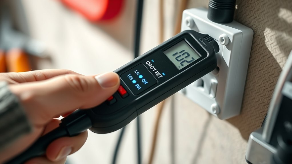
Before testing, choose a circuit tester that matches the job and the circuit’s voltage. For basic household checks, you might select a noncontact voltage tester or a two-pole tester.
Choose a tester suited to both the task and the circuit’s voltage for safer, more reliable household checks.
Choose a multimeter when you need broader measurement options, but confirm that its ratings suit the circuit. Look for clear voltage limits, insulated probes, sturdy construction, and a recognized safety certification.
If you’ll work in a damp area, use equipment specifically approved for that environment, and inspect the tester before each use.
Circuit tester history explains why today’s tools vary widely: older designs often relied on simple lamps, while modern testers may add digital displays and protective features.
Don’t let common misconceptions guide your choice. A higher price doesn’t automatically mean greater safety, and a tester designed for low-voltage electronics may not protect you on household wiring.
Read the manufacturer’s instructions, match the tool to your task, and replace any tester with damaged leads, cracked housing, or uncertain ratings.
Learn What Your Tester Detects
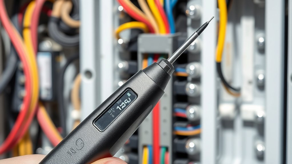
A circuit tester detects specific electrical conditions, not every possible fault. Before you use it, learn what its design can reveal.
A voltage tester identifies voltage between a conductor and a reference point, while a continuity tester indicates a complete, low-resistance path.
Some testers detect alternating current without touching exposed metal. Others measure direct current, resistance, or polarity.
Read the symbols, ranges, and terms in the instructions so you’ll know what each result means.
Testing circuit diagrams helps you predict where voltage should appear and which paths should remain continuous.
Compare those expectations with your tester’s function, rather than treating every reading as proof of a defect.
A no-voltage result might indicate an open switch, a disconnected conductor, or a condition outside the tester’s range.
Understanding tester limitations keeps you from confusing an undetected problem with a safe circuit.
Check the Circuit Tester Before Use
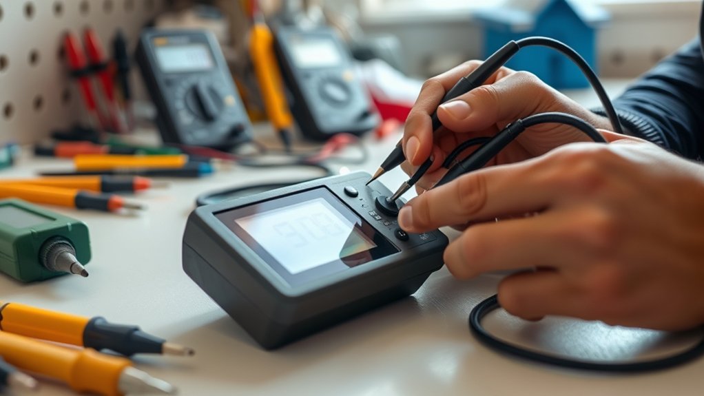
Once you know what the tester can detect, check that it works properly before connecting it to the circuit. Inspect the housing, leads, probes, display, and insulation for cracks, looseness, corrosion, or exposed wire. Don’t use the tool if any part looks damaged.
Inspect the tester for damage and verify its operation before connecting it to any circuit.
Confirm battery compatibility with the manufacturer’s specifications. Install fresh batteries with the correct type, orientation, and charge level, then switch the tester on. Make sure the display, indicator light, buzzer, and controls respond normally.
If the device shows a low-battery warning, replace the batteries before continuing.
Review the required calibration procedures in the instruction manual. Some testers need a zero adjustment, reference check, or self-test before each session.
Follow those steps precisely, and compare the result with a known safe reference when the manufacturer recommends it. Set the correct measurement mode and range, but leave the tester disconnected until you’ve completed these checks.
This preparation helps prevent false readings and protects both you and the instrument.
Find the Circuit and Test Points
Start by identifying the circuit you need to test and locating its accessible test points, such as terminals, connectors, or exposed contacts. Use the vehicle, appliance, or equipment’s Circuit diagram to trace the circuit path and understand which points represent power, ground, input, and output.
Don’t rely on wire color alone, because colors can vary between models or installations. Check labels, terminal numbers, and the manufacturer’s service information to confirm each location.
Look for safe access points that won’t require removing protected covers or disturbing nearby wiring. Before taking measurements, review the expected voltage, resistance, or continuity for the section you’re examining.
Confirm your Tester calibration and select the appropriate measurement function and range for those values. Keep your planned test points clearly identified, and note their relationship to the suspected fault.
You’ll then know exactly where measurements belong, without guessing or risking contact with unrelated circuits. Make certain lighting is adequate and keep the diagram visible while you work.
Connect the Tester Probes Correctly
Connect the red probe to the positive terminal and the black probe to the negative terminal. Make sure both probes are secured firmly so they maintain steady contact. This will help you get an accurate reading and prevent reversed results.
Identify Positive And Negative
To identify positive and negative terminals, place the tester’s red probe on the suspected positive terminal and the black probe on the negative terminal or a known ground. Then read the tester’s display or indicator:
- A positive voltage reading usually confirms that the red probe touches the positive terminal while the black probe touches negative or ground.
- A negative reading means the probe positions are reversed; switch them to achieve correct polarity.
- A zero or very low reading may indicate no voltage, an open circuit, or an incorrect test point.
Use Positive identification to verify the red lead’s connection and Negative confirmation to check the black lead’s reference. Compare your result with the circuit diagram or device markings.
Don’t rely on probe color alone, since wiring may not follow standard conventions.
Secure Probe Connections
Secure probe connections before taking a reading so the tester measures the circuit accurately. Turn off power when required, then insert the black probe into the COM port and the red probe into the correct voltage, resistance, or current port.
Push each plug firmly; a loose connection can create unstable readings or damage the tester. Touch the black probe to the circuit’s negative or ground point and the red probe to the positive test point.
Keep your fingers behind the probe guards, and don’t let the metal tips contact each other. Before testing, inspect the leads for cracks or exposed wire.
Check Battery compatibility, because incorrect batteries can affect accuracy or safety. If your tester supports Probe calibration, calibrate it according to the manual.
Select the proper range, then read the display steadily.
Test for Voltage Safely
Before testing, turn off power when possible, inspect the circuit tester for damage, and confirm it works on a known live circuit. Wear insulated shoes, remove jewelry, and keep your hands dry. Review the circuit design so you understand which conductors may carry energy and where voltage regulation equipment connects.
Prepare safely: inspect and verify your tester, wear protective gear, keep dry, and understand the circuit before testing.
- Set the tester to the correct voltage type and range. Use an approved meter rated for the circuit’s category and maximum voltage.
- Hold only the insulated probe handles. Touch the probes to the intended points without allowing their tips, your body, or loose leads to bridge terminals.
- Stand to the side of the panel, keep your face away, and apply one hand when practical. Stop immediately if you notice heat, sparks, odors, damaged insulation, or unstable equipment.
Don’t test in wet or crowded conditions. Follow the manufacturer’s instructions and local electrical rules. If you’re unsure about the circuit or its rating, de-energize it and call a qualified electrician.
Read Circuit Tester Results
Read the voltage displayed on your circuit tester and compare it with the expected value. Also, watch for continuity signals, such as a beep or illuminated indicator, to confirm that the circuit path is complete.
Then, use these results to identify energized circuits and locate any possible breaks.
Interpret Voltage Readings
Interpreting voltage readings tells you whether a circuit has the correct electrical potential at each test point. Set your tester to the appropriate voltage range, then compare the display with the circuit’s expected value. Keep your probes steady and observe the reading before drawing conclusions.
- A normal reading closely matches the rated voltage, showing that power reaches that point.
- A low reading may indicate a weak supply, loose connection, excessive circuit resistance, or an overloaded component.
- A high reading can signal a regulator problem, incorrect connection, or open load.
Watch for voltage fluctuation rather than judging one instant. Small changes may be normal, but rapid or wide swings suggest unstable power or intermittent contact.
Record each measurement and compare it with nearby test points to locate the affected section. Always follow the tester’s polarity markings and safety limits.
Identify Continuity Signals
To identify continuity signals, set the circuit tester to continuity mode and touch the probes together first. You should hear a beep or see a continuity symbol, confirming that the tester works.
Next, disconnect power from the circuit, then place one probe on each end of the wire, fuse, or connection. A beep or low resistance reading indicates a complete path.
No sound, an open-circuit symbol, or a very high reading suggests a break. Check both probe tips for secure contact before judging the result.
Voltage fluctuations can create misleading readings, so never test continuity on an energized circuit. Inspect Circuit insulation for cracks, cuts, or melted areas that could cause shorts.
If results seem inconsistent, retest the component and compare it with its specified resistance.
Test Outlets, Wires, and Fuses
Once you’ve confirmed the tester works, use it to check outlets, wires, and fuses for voltage or continuity. Wear insulated gloves, keep your fingers behind the probe guards, and follow the manufacturer’s instructions.
Turn power off before continuity tests, and never touch exposed metal during voltage checks.
- Outlets: Set the tester for voltage, insert the probes into the hot and neutral slots, and compare the reading with the outlet’s rated voltage. Test hot-to-ground as well, keeping the probes steady.
- Wires: De-energize the circuit, disconnect the wire from connected components, and test each end for continuity. Inspect wire insulation for cuts, scorching, or loose sections, and use circuit diagrams to identify the correct conductors.
- Fuses: Remove the fuse before testing. A continuity tone or near-zero resistance usually indicates an intact fuse; no tone or an open reading indicates a break.
Place probes carefully and avoid shorting terminals. Restore connections securely after testing, and record each result clearly for your repair notes.
Double-Check Surprising Readings
If a reading surprises you, check the voltage source before assuming there’s a fault in the circuit. Make sure the ground connections are secure, then retest the circuit under load to confirm the result.
Verify Voltage Sources
When a circuit tester shows an unexpected voltage, verify the source before diagnosing the circuit. Confirm your tester works correctly by checking it on a known, properly rated supply. Inspect the probes, leads, battery, and selected measurement mode for damage or incorrect settings.
Then repeat the reading at the same source, keeping your fingers behind the probe guards.
- Compare the reading with the source’s labeled voltage or wiring diagram.
- Test a second known source with the same meter setting.
- Use another reliable tester to confirm unusual results.
Watch for voltage fluctuations caused by switching loads, loose connections, or a weak power supply. If readings still differ, stop circuit troubleshooting until you identify the discrepancy.
Never assume a zero or high value means the circuit itself has failed. De-energize equipment before changing leads, ranges, or connections, and follow the manufacturer’s safety limits.
Check Ground Connections
After verifying the voltage source, check the circuit’s ground connections before treating a surprising reading as a fault. Set your circuit tester to the appropriate function, then place one probe on the suspected ground and the other on a known-good reference point.
A stable, near-zero reading usually indicates a solid connection. A fluctuating or unexpectedly high reading may reveal corrosion, a loose terminal, a broken conductor, or a ground fault.
Turn off power before tightening connections or inspecting exposed wiring. Clean contact points, secure fasteners, and trace the conductor back to its grounding point.
Use your tester to compare each section and confirm wiring integrity. Don’t assume the component has failed until you’ve ruled out a weak ground.
Careful checks prevent misdiagnosis and protect connected equipment from unsafe current paths.
Retest Under Load
Retest the circuit under its normal load to confirm that a surprising reading reflects real operating conditions. A disconnected circuit may show normal voltage, while a working device reveals voltage fluctuations or a weak connection. Keep your tester leads secure, select the correct range, and avoid touching exposed metal.
- Turn on the equipment and observe the reading as it starts and runs.
- Compare the loaded measurement with the no-load result; a sharp drop can indicate resistance, a failing supply, or loose wiring.
- Check again at the source and load terminals to locate where voltage disappears.
If the value changes repeatedly, watch for switching devices or intermittent faults. Don’t assume every low reading means circuit overloads; verify the equipment’s current draw and inspect fuses, connectors, and grounds. Disconnect power before repairs, then retest to confirm your correction.
Follow Circuit Tester Safety Rules
Before testing, switch off power when possible, inspect the tester for damage, and confirm its voltage rating matches the circuit. Wear insulated gloves and safety glasses, and remove jewelry that could contact energized parts.
Never use a tester with cracked insulation, loose leads, or a damaged probe. Set the selector correctly before connecting it, and hold probes behind their finger guards.
Keep your hands dry, maintain a stable stance, and avoid touching metal contacts. If you must test live voltage, tell others nearby and keep the work area clear.
Use one hand when practical to reduce a current path through your chest. Check the circuit breaker and lock it out before servicing conductors.
Don’t rely on appearance alone. Verify de-energization with a known live source, test the circuit, then retest the source.
For insulation resistance tests, disconnect sensitive electronics first and follow the meter’s voltage limits. Stop immediately if readings or conditions seem unsafe, and call a qualified electrician.
Frequently Asked Questions
How Often Should a Circuit Tester Be Calibrated?
You should calibrate a circuit tester at least once a year, or according to the manufacturer’s Calibration schedule. Increase frequency if you use it daily, expose it to heat, moisture, vibration, or drops, or rely on it for safety-critical measurements.
Check its accuracy before important work and after damage. Follow approved Calibration methods, using a certified reference or laboratory service.
Don’t use the tester if readings seem inconsistent; calibrate or replace it promptly.
Can Circuit Testers Detect Resistance or Continuity?
Yes, many circuit testers detect continuity, but only some measure resistance. About 90% of basic testers focus primarily on voltage measurement, so you’ll need a multimeter for accurate resistance readings.
Set your multimeter to continuity mode; it’ll beep when a low-resistance path exists. For resistance, choose ohms and connect the probes across the component.
You can then support fault diagnosis by identifying breaks, shorts, and unexpectedly high resistance.
What Is the Difference Between Analog and Digital Circuit Testers?
Analog and digital circuit testers differ mainly in display, precision, and functionality. With an analog tester, you read a moving needle, so you’ll notice gradual changes but may estimate values.
A digital tester shows numbers clearly, improving Tester Accuracy and reducing reading errors. Analog models often handle fluctuating signals intuitively, while digital models commonly offer auto-ranging, continuity alerts, and extra measurements.
For Analog versus Digital comparisons, choose analog for trends and digital for precise results.
How Should You Store a Circuit Tester After Use?
Store your circuit tester in a clean, dry case after use, because the moment you need it most often follows the moment you put it away. For storage safety, disconnect probes, remove batteries if you won’t use the tester soon, and keep it away from heat, moisture, dust, and children.
Proper maintenance includes coiling leads loosely, inspecting insulation, wiping the housing, and checking calibration before your next measurement.
Can a Circuit Tester Test Automotive Electrical Systems?
Yes, you can use a circuit tester for basic automotive diagnostics and electrical troubleshooting. You can check fuses, switches, wires, sockets, and power or ground connections in 12-volt systems.
First, connect the tester’s clip to a suitable ground, then touch the probe to the circuit. Follow your vehicle’s service manual, avoid airbag wiring, and use a multimeter for precise voltage, resistance, or current measurements. Always work carefully around moving parts.
Conclusion
Using a circuit tester isn’t rocket science—it’s like following a small trail of electrical breadcrumbs. Choose the right tester, understand what it detects, and check it before use.
Then find your test points, connect the probes correctly, and read the results carefully. Whether you’re checking outlets, wires, or fuses, double-check anything surprising.
Above all, follow safety rules. With patience and care, you’ll keep sparks where they belong and make learning how a circuit tester works feel far less intimidating.