

How Does a Relay Tester Work Step by Step
Testing relays can be frustrating, especially when you’re unsure whether the problem is the coil, contacts, or wiring. You’re not alone—many people struggle to diagnose relay faults quickly, which is why choosing the best relay tester can make troubleshooting much easier.
A relay tester works by checking the relay’s coil and contacts in sequence. First, you identify the coil, common, normally open, and normally closed pins, then compare their ratings with the tester.
With power disconnected, you measure coil resistance for opens or shorts. Next, you connect the relay securely, select the correct settings, and apply its rated voltage.
The tester confirms switching, timing, continuity, and contact resistance. These steps help you diagnose common faults and determine whether replacement is necessary.
Key Takeaways
- Identify the relay’s coil, common, normally open, and normally closed terminals using its diagram or datasheet.
- Check coil resistance with a multimeter, comparing the reading against the manufacturer’s specified value.
- Connect the relay securely to the tester and select settings matching its voltage, contact configuration, and ratings.
- Apply the rated coil voltage while monitoring current, energization, timing, noise, and overheating.
- Verify contact switching and resistance, then compare results with specifications to diagnose faults or approve operation.
What Does a Relay Tester Measure?

A relay tester measures how accurately a relay responds to electrical inputs and controls its output. You use it to verify whether the relay coil receives the required voltage and draws an appropriate current. The tester also checks coil resistance, helping you spot an open winding, a short circuit, or excessive electrical load.
Next, the instrument monitors switching behavior. It confirms that the contacts close when you energize the coil and open when you remove power. By measuring timing, the tester can reveal delayed operation, contact bounce, or inconsistent switching.
A relay tester verifies switching behavior, timing, and contact consistency by monitoring how contacts respond to coil energization and power removal.
You can also evaluate contact durability through repeated test cycles, which shows whether the relay maintains reliable performance under regular use. Many testers record results digitally, letting you compare measurements against expected values.
They may flag unstable readings or excessive resistance at the contacts. This process helps you judge operating reliability without relying solely on visual inspection or guesswork.
Identify the Relay’s Pins and Ratings
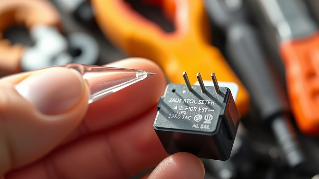
Before testing, identify the relay’s pin layout so you can distinguish the coil, common, normally open, and normally closed terminals. Then check its voltage and current ratings to ensure the tester uses safe, suitable values. This helps you connect the relay correctly and avoid damage.
Pin Layout Identification
Pin layout identification starts with locating the relay’s terminal diagram, usually printed on its case or shown in the service manual. Match each numbered terminal to its function before connecting your relay tester.
You’ll typically find the relay coil terminals, common (COM), normally open (NO), and normally closed (NC) contacts. Don’t assume physical position; manufacturers arrange pins differently.
| Pin marking | Function | Tester connection |
|---|---|---|
| 85 | Coil terminal | Coil lead |
| 86 | Coil terminal | Coil lead |
| 30 | Common contact | COM lead |
| 87 | Normally open | NO lead |
Check the diagram for polarity markings, especially with diode-equipped relays. Identify contact paths with the relay de-energized and energized.
Observe contact bounce during switching, but don’t confuse it with an incorrect pin assignment. Record the layout before testing.
Voltage and Current Ratings
Once you’ve identified each terminal, check the relay’s coil voltage and contact current ratings against your tester’s specifications. Confirm that the coil rating matches the tester’s available output, such as 5, 12, or 24 volts.
Then verify that the tester can safely handle the relay’s switching current and voltage. Review the relay specifications before connecting anything, because exceeding either limit can damage the tester or relay.
- Match the coil voltage to the tester’s setting.
- Confirm contact ratings for AC or DC loads.
- Check normally open and normally closed terminals.
- Use a suitable load during contact testing.
- Follow the manufacturer’s testing procedures.
Don’t apply power until you’ve confirmed polarity, pin identity, and rating compatibility. If the relay’s values remain unclear, consult its datasheet rather than guessing.
Proper rating checks keep measurements accurate and prevent unsafe operation.
Measure Coil Resistance Before Testing

Check the relay coil’s resistance with a multimeter before connecting it to the tester. This quick check helps you identify an open coil, a short circuit, or an unsuitable relay before further testing.
Turn off all power, remove the relay from any circuit, and set your multimeter to the resistance (Ω) range. Touch one probe to each coil terminal, keeping your fingers away from the metal tips.
Compare the displayed reading with the resistance value listed on the relay or in its datasheet.
A reading near infinity usually indicates a broken winding or damaged coil insulation. A reading far below the specified value may indicate internal shorting, which can cause excessive current.
If the resistance falls within the stated tolerance, the winding likely has acceptable electrical conductivity. Also check for unstable readings by holding the probes steadily for several seconds.
Record the measured value so you can compare it with later observations and spot changes accurately.
Connect the Relay to the Tester
With the tester switched off, connect each relay terminal to the matching socket or lead according to the tester’s wiring diagram. Identify the relay coil pins first, then align them with the tester’s coil connections. Avoid forcing the relay into a socket; the pin layout should match naturally.
- Match the relay’s part number and pin markings.
- Connect coil pins to the designated coil leads.
- Attach contact terminals to their corresponding outputs.
- Push each connection firmly into place.
- Keep wires clear of moving or exposed conductors.
Check that every terminal sits securely and that no plug touches an adjacent connection. If your relay uses a removable adapter, select the adapter that fits its base and verify its orientation before inserting it.
Handle the relay by its housing rather than pulling on its pins. Don’t apply power while you’re still checking connections. A correct connection protects the tester, prevents misleading results, and gives you a stable setup for the next testing step.
Leave the tester controls untouched until all wiring looks correct.
Choose the Correct Relay Tester Settings
Select the tester settings that match the relay’s type, coil voltage, and contact arrangement before applying power. Check the relay’s label or datasheet, then choose the corresponding mode on your tester.
Select SPDT, SPST, normally open, or normally closed contact options accurately so the instrument can interpret switching behavior correctly. Set the expected coil resistance range when available, and confirm the tester’s measurement units.
| Relay detail | Setting to choose | Why it matters |
|---|---|---|
| Coil voltage | Rated voltage value | Prevents incorrect test criteria |
| Contact arrangement | SPST, SPDT, or other | Matches switching configuration |
| Coil resistance | Suitable resistance range | Identifies open or shorted coils |
Review the testing procedures for your specific tester, because menu names and automatic checks can differ. If you’re performing Relay calibration, verify the instrument’s reference settings and measurement accuracy first.
Recheck every selection against the relay documentation. Don’t guess from appearance alone; similar relays may use different ratings or contact layouts.
Correct settings help produce dependable results and protect the tester during later steps.
Apply Voltage to the Relay Coil
After confirming the tester settings, connect the relay coil to the tester’s output terminals and apply the relay’s rated voltage. Assure the selected voltage matches the relay’s specifications, whether AC or DC.
Applying excessive voltage can overheat the winding, while insufficient voltage may prevent reliable operation. Watch the tester’s readings as it energizes the Relay coil.
Current should rise within the expected range, indicating that the winding is receiving power. As voltage passes through the coil, it creates a Magnetic field that pulls the internal armature.
Keep your hands clear of exposed terminals, and stop the test immediately if you notice smoke, unusual noise, or excessive heat.
- Verify the relay’s rated voltage and current.
- Select the correct AC or DC supply.
- Connect leads firmly to the coil terminals.
- Increase voltage smoothly when the tester allows it.
- Record voltage and current readings for comparison.
Let the tester complete its energizing cycle before removing connections. This controlled step confirms the coil receives power safely without evaluating contact behavior.
Monitor Normally Open and Closed Contacts
Next, monitor the relay’s contacts as the coil energizes. Verify that the normally open contacts close and carry the expected signal. Then, check that the normally closed contacts open as specified.
Verify Normally Open Contacts
To verify normally open contacts, connect the relay tester’s leads to the designated terminals and monitor the continuity reading while the relay is de-energized and energized. With the relay coil inactive, the tester should show an open circuit.
Apply the specified control voltage, then confirm that the contacts close and continuity appears. Check that the reading remains stable rather than fluctuating.
Contact wear, contamination, or insufficient coil voltage can prevent reliable closure.
- Identify the correct normally open terminals.
- Record the initial open-circuit reading.
- Energize the relay using its rated voltage.
- Confirm continuity across the contacts.
- Compare results with the manufacturer’s specifications.
If the contacts don’t close, remove power and inspect connections before repeating the test. Don’t exceed the relay’s voltage rating, and use the tester’s audible mode only as a convenient confirmation, not as your sole diagnostic result.
Check Normally Closed Contacts
With the relay de-energized, connect the tester to the normally closed terminals and confirm that it shows continuity. This result indicates that the contacts remain closed in their resting state.
Next, energize the relay using the tester’s control function or an approved power source. The continuity reading should disappear, proving that the contacts opened correctly.
De-energize the relay and verify that continuity returns. If the circuit stays open, inspect for contact corrosion, which can increase resistance or prevent reliable closure.
Also check for mechanical wear, including pitted surfaces, weakened springs, or misalignment. Wiggle the relay gently while monitoring the reading to reveal intermittent connections.
Record each result, then compare it with the relay’s specifications. Replace the relay if switching remains inconsistent, resistance exceeds limits, or the contacts fail to reset.
Measure Contact Resistance Under Load
Once the relay closes, the tester applies a controlled load through its contacts and measures the resulting voltage drop. You use this reading to calculate contact resistance accurately, even while current flows.
Measure voltage drop under a controlled load to calculate relay contact resistance accurately during operation.
A low, stable value shows efficient conduction; a higher value indicates increased resistance that can affect circuit performance. The tester may repeat the measurement at several load levels, helping you observe how the contacts behave during operation.
- Select the specified test current.
- Connect the load leads securely.
- Measure voltage across the closed contacts.
- Calculate resistance using Ohm’s law.
- Compare results with the rated limit.
Relay automation lets you schedule repeated measurements and record trends without manual switching. As you review the results, consider contact wear, contamination, or heat-related changes that may raise resistance over time.
Keep probes clean, use correct lead placement, and allow the tester to stabilize before accepting each reading. This process gives you a dependable measurement of real operating performance without relying solely on an unloaded continuity check.
Record the measured value, test current, and ambient conditions for later reference.
Diagnose Common Relay Faults
Start by identifying the symptoms of the fault, such as clicking, sticking, or intermittent operation. Then, use the relay tester to check continuity across the relay’s contacts and coil. These tests can help you determine whether the relay has an open circuit, welded contacts, or another problem.
Identify Fault Symptoms
Before testing, identify symptoms that point to a faulty relay, such as intermittent operation, a load that won’t turn on, rapid clicking, overheating, or a blown fuse. These signs help you narrow the problem before connecting a relay tester.
Listen, observe, and compare the relay’s behavior with normal system operation.
- A silent relay may indicate a damaged relay coil or missing control power.
- Rapid clicking can suggest unstable voltage or a weak coil.
- A load that stays on may indicate welded contacts.
- Overheating can point to excessive current or a poor contact gap.
- A blown fuse may signal a shorted load or relay fault.
Record when each symptom occurs, including temperature and operating conditions. Don’t remove the relay yet; preserve the evidence for the next diagnostic step.
Test Relay Continuity
With the relay removed and its terminals identified, test continuity to determine whether the coil and contacts operate correctly.
Set your multimeter to resistance mode, then touch the probes to the relay coil terminals. Compare the reading with the manufacturer’s specified resistance.
Infinite resistance indicates an open coil, while a near-zero reading suggests a short.
Next, perform contact testing by checking the normally open and normally closed terminals without power. The normally open pair should show no continuity, and the normally closed pair should show continuity.
Apply the relay’s rated control voltage, then repeat the checks. The normally open contacts should close, while the normally closed contacts should open.
If readings don’t change, fluctuate, or contradict specifications, replace the relay because its contacts or relay coil has failed.
Interpret Results and Replace the Relay
Once the relay tester completes its checks, compare the measured results with the relay’s specifications to identify a pass or failure. Check the relay coil’s resistance, operating voltage, and switching response.
Then inspect contact wear, because pitted, burned, or welded contacts can cause unreliable operation even when continuity appears normal.
- Confirm coil resistance falls within the manufacturer’s stated range.
- Verify the relay energizes at the specified control voltage.
- Check normally open and normally closed contacts for correct switching.
- Look for excessive contact wear, corrosion, cracks, or heat damage.
- Record the result before removing or replacing the relay.
If every measurement matches the specifications, reinstall the relay and secure each connection.
If any value falls outside the acceptable range, switch off power and replace the relay with an identical type. Match the coil voltage, contact arrangement, current rating, and pin layout.
After installation, repeat the tester’s checks and operate the equipment to confirm reliable switching. Dispose of the failed relay according to local electronic-waste requirements.
Frequently Asked Questions
Can Relay Testers Safely Test Solid-State Relays?
Yes, relay testers can safely test solid-state relays when you use a compatible model and follow the manufacturer’s limits. Unlike electromechanical devices, solid-state relays may require specific input voltages, load types, and testing procedures.
During relay testing, verify polarity, isolate power, and avoid exceeding rated current or voltage. Safety considerations include using proper protection, checking heat buildup, and confirming that your tester supports semiconductor switching rather than relying on coil-based tests alone.
How Often Should a Relay Tester Be Calibrated?
Calibrate your relay tester at least annually, but shorten that interval when you use it heavily, transport it often, or work in harsh conditions. Precision versus drift defines relay tester accuracy: a fresh calibration protects confidence, while neglected equipment quietly creates uncertainty.
Follow the manufacturer’s guidance and your quality system, then verify performance before critical testing. Calibration frequency may also increase after repairs, overloads, failed checks, or exposure to extreme heat, moisture, or vibration.
What Safety Precautions Are Needed When Testing Automotive Relays?
You need relay safety and testing precautions before checking automotive relays. Turn off the ignition, disconnect the battery when appropriate, and consult the vehicle’s wiring diagram.
Wear eye protection, keep tools insulated, and never bypass a relay with unknown terminals. Set your tester correctly, inspect leads for damage, and avoid short circuits.
Don’t work near fuel vapors or moving parts. If readings seem abnormal, stop and seek professional help.
Can a Relay Tester Identify Intermittent Relay Failures?
Yes, a relay tester can identify some intermittent relay failures, but it can’t guarantee detection every time. It repeatedly energizes the relay, monitors coil resistance, contact continuity, and switching behavior, then reveals faults that appear only under repeated cycles.
However, heat, vibration, or vehicle wiring problems may trigger symptoms the tester misses. You’ll improve testing accuracy by combining repeated bench tests with in-vehicle checks.
Strong relay durability reduces, but doesn’t eliminate, intermittent failures.
Are Universal Relay Testers Compatible With Every Relay Socket?
No, universal relay testers aren’t compatible with every relay socket. You’ll need to verify pin count, terminal layout, coil voltage, contact configuration, and physical dimensions before connecting one.
Relay socket compatibility depends on the tester’s adapters and the relay design, not just the tester’s label. Universal testing standards can support common automotive or industrial relays, but they don’t guarantee universal fit.
Always check the manufacturer’s compatibility chart and use the correct adapter.
Conclusion
You’ve seen how a relay tester checks coil resistance, energizes the relay, and verifies contact operation under load. Remember, one faulty relay can interrupt an entire circuit, yet testing usually takes less than five minutes.
By comparing each reading with the manufacturer’s specifications, you’ll quickly distinguish a weak coil, stuck contact, or excessive resistance from a healthy relay. Test carefully and record your results.
Replace any relay that fails even one essential check before it causes a larger electrical problem. Following these steps helps ensure your relay tester confirms reliable relay operation.